Dingfeng Capacitor---Preventing capacitor arcing in ever-smaller high-voltage automotive designs
- Share
- publisher
- Alice Yang
- Issue Time
- Oct 21,2016
Dingfeng Capacitor-----Preventing capacitor arcing in ever-smaller high-voltage automotive designs
The inverters and charging systems in hybrid or fully electric vehicles provide a topical example of a high-voltage application that faces extreme space constraints. When multilayer ceramic capacitors (MLCs) are used as filters across high-voltage lines, pressure to miniaturize can lead designers to select devices in the smallest available cases, such as 0603. A 0603 chip saves 75% of the board space occupied by a 1206 MLCC. However, these smaller cases challenge device manufacturers to maximize capacitance within the reduced package volume and to ensure reliability.
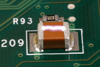
The shorter distance between the device terminals will bring about reliability concerns due to a greater risk that creepage — the natural tendency of an electric field to spread out over a dielectric surface — may allow arcing between the capacitor terminals (Fig. 1) when the full working voltage is applied. This usually results in failure of the capacitor and may cause thermal damage to other nearby components. Factors such as high atmospheric humidity or contamination on the component surface further increase the likelihood of arcing.
FAJH03_Capacitor_1_Oct2016
Fig. 1: White streak is surface arcing between MLCC terminations.
Analysis of arcing phenomenon
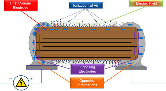
When a high-voltage dc bias is applied to an MLCC, an electric field concentration is localized in the termination area and respective first counter electrode within the MLCC, as illustrated in Fig. 2. The difference in potential begins to build along the surface of the chip, ionizing the air above it once the electrical breakdown of air is reached.
FAJH03_Capacitor_2_Oct2016
Fig. 2: Electrical conditions around the capacitor surface that can allow arcing to occur.
Once the inception voltage of the ionized air is reached, a conductive path is created, allowing the energy in the concentrated electric field of the termination area to discharge. This discharge travels through the air along the surface of the capacitor and onto an area of lower potential rather than through the capacitor. During discharge, there is a visible and audible electric arc across the surface of the chip.
This type of arcing can occur at applied voltages of about 300 V. For some high-voltage capacitors, this may be lower than the rated voltage of the device. If the arcing occurs between a termination surface and through the dielectric material of the ceramic body to the first internal counter electrode, this usually causes a dielectric breakdown of the capacitor, resulting in a short-circuit condition that leads to catastrophic failure.
Prevention of arcing
Capacitor vendors have tried a number of approaches to prevent arcing. One of these is to apply a polymer or glass coating along the surface of the chip to fill any voids and provide a smooth surface that has a naturally lower susceptibility to creepage.
Filling these voids with insulating material also helps to exclude contaminants and improves the dielectric stability across the surface of the chip. Improving this stability reduces the ionization of the air and increases the inception voltage along the surface.
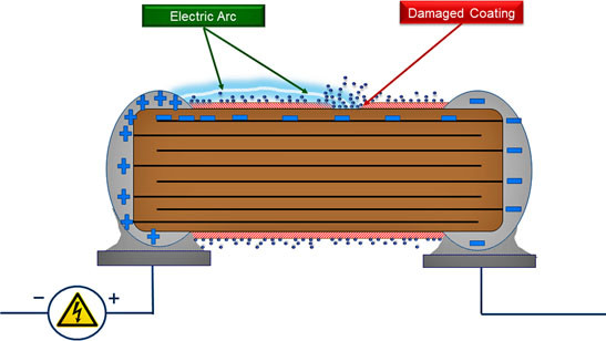
Designers have used surface coatings on PCBs in high-voltage applications for decades. This technology has been proven effective but with a primary disadvantage of cost of applying the coating. Designers will avoid such costs unless it is deemed absolutely necessary to meet specific electrical safety standards. Another hazard is that surface coatings can be damaged during the handling and assembly processes. A breach in the coating reduces the creepage distance capability and makes the capacitor susceptible to contamination and arc-over (Fig. 3). In addition, when choosing a device that has a pre-applied coating, it is important to ensure that the coating material is compatible with all applicable assembly materials, processes, and conditions. Incompatibility could result in premature failure of the surface coating.
There are also concerns with air gaps under mounted components and voids in and under the epoxy coating. These gaps and voids allow for the same arcing potential as an uncoated device.
FAJH03_Capacitor_3_Oct2016
Fig. 3: Imperfections in the coating can leave the device vulnerable to arcing.
Series Electrode
An alternative technique, illustrated in Fig. 4, is “series-electrode” construction. The first part of the diagram illustrates how five individual 1,000-V 1,000-µF capacitors can be connected in series to form an array that raises the breakdown capability to 5,000 V even though the total electric field experienced is the same as that for a single capacitor. However, a big disadvantage is that the total capacitance is reduced to 200 µF. The second part of the diagram shows the entire block of capacitors placed into a single monolithic structure with the same characteristics as the five series devices.
FAJH03_Capacitor_4_Oct2016
Fig. 4: Top — Five individual capacitors in series. Bottom — Monolithic series-electrode construction raises the breakdown voltage but, like the individual, reduces capacitance.
A number of manufacturers, including KEMET, have implemented floating-electrode, or serial-capacitor, technology in a number of device families covering low- to mid-capacitance values. These devices feature a cascading internal electrode design that effectively forms multiple capacitors in series within the device. While certainly reducing susceptibility to surface arcing, this type of series connection is also highly effective as a flex-crack mitigation technology that reduces the risk of capacitor short-circuit failure. A flex crack cannot cross electrodes at both ends of the capacitor. It can only cross electrodes that originate from one end of the capacitor and those floating between the active areas. Even if a crack propagates through one of the active areas, the device may lose capacitance but will not typically fail short because there is no conductive pathway between the electrodes connected to the opposed terminations. For this reason, the floating electrode fails open.
ArcShield technology
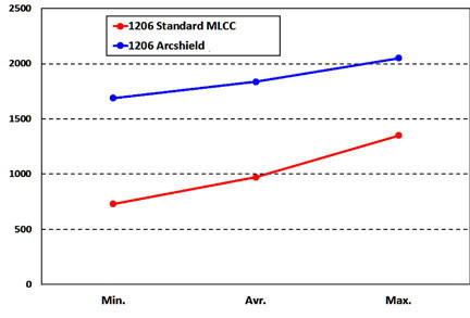
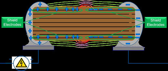
ArcShield capacitor designs use an additional internal shield electrode, as shown in Fig. 5, which opposes the effects that can cause surface arcing without the disadvantages of a coating or serial-electrode construction. In a standard design, the electric field at the surface is very close to the terminal, while the ArcShield design has a larger energy barrier because of the presence of the shield electrode of similar polarity to the termination.
FAJH03_Capacitor_5_Oct2016
Fig. 5: The shield electrode reduces field strength in the region of the capacitor surface and first counter
electrode.
When a high-voltage bias is applied to an ArcShield MLCC, a potential difference is established between the opposing terminations and the opposing electrode structure, but the electric field concentration is localized to the shield electrodes rather than to the termination surface and respective first counter electrode. This minimizes the difference in potential along the surface of the chip and drastically improves the creepage distance capability even in smaller cases and when there is high porosity in the dielectric surface.
FAJH03_Capacitor_6_Oct2016
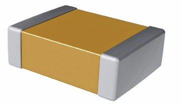
Fig. 6: ArcShield capacitors come in standard packages.
Review of shield effects
A standard overlap X7R MLCC is vulnerable to three basic high-voltage failure mechanisms. These are arcing between a terminal and the nearest electrode of opposite polarity, arcing between terminals, and internal breakdown.
ArcShield ceramic capacitors address these failure mechanisms by adding a shield electrode, which prevents arcing between terminals and any nearby opposing electrode. The devices also incorporate thicker active areas that effectively increase the breakdown voltage.